This section describes how to design a ripple-carry adder in Lava that uses the Virtex carry chain. This component is widely used in many other Lava examples. First we present how to describe a one-bit adder cell using the regular netlist style. Then we use layout combinators to create a vertical column of these cells that make up a carry-chain ripple-carry adder.
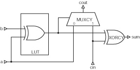
A one-bit adder can be accommodated in one half of a slice using just one function generator as a LUT, one MUXCY and one XORCY. For this reason we will describe the one-bit adder in netlist style. A schematic for a one-bit carry chain adder is shown below.
A column layout combinator will be used later to tile several one-bit adders vertically to make an n-bit adder. Before we tile the one-bit adder vertically we have to carefully consider which sides of the tile the signals are connected to. We shall assume a left to right data flow with the two bits to be added connected to the left hand side of the tile and the sum bit appearing from the right hand side of the tile. Since the carry must flow upwards in the Virtex architecture the cin signal must come into the bottom of the tile and the cout signal must emerge from the top of the tile. This gives the following four-sided tile orientation:
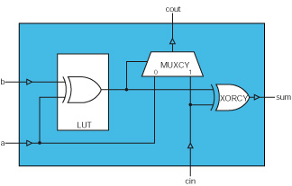
This four-sided tile represents a circuit with input ((a,b), cin) because (a,b) is the left input and cin in the bottom input. This tile also has the output (sum, cout) because sum is the right output and cout is the top output. This fixes the type for this one-bit adder adder tile which can now be described as a Lava netlist as follows:
oneBitAdder :: (Bit, (Bit, Bit)) -> (Bit, Bit)
oneBitAdder (cin, (a,b))
  = (sum, cout)
    where
    part_sum = xor2 (a, b)
    sum = xorcy  (part_sum, cin)
    cout = muxcy (part_sum, (a, cin))
This is very similar to what one would write in VHDL or Verilog except that the instance names are anonymous. Furthermore, the Lava description includes information in the shape of the types that indicates which faces of the tile signals occur and in what order. This is essential in order to compose tiles using combinators which automatically glue together circuit interfaces and layout out circuits in specific patterns.
To make a 4-bit adder all we need to do is to tile vertically four one-bit adder tiles:
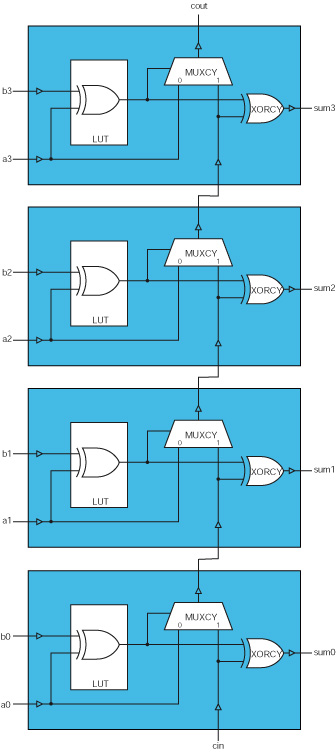
In a conventional HDL this can be described either by copying and pasting the instantiating code for each one-bit adder and then naming intermediate nets which cause components to be connected together to form the composite four-bit adder netlist. Constructs like for...generate in VHDL help to capture such repetition more concisely but internal nets still have to be named and there is no information about layout. The Lava description of the circuit show above is simply:
col 4 oneBitAdder
This is much more concise than equivalent conventional HDL descriptions. It also includes information about layout: the first one-bit adder tile is at the bottom and then the other are stacked on top of it in sequence (RLOCs are generated to enforce this layout). Internal nets are anonymous and circuits are composed automatically by taking the input from below and attaching it to the carry input of the tile.
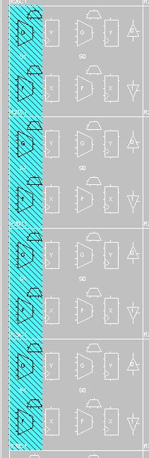
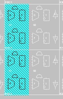
An example Virtex layout of a 8-bit adder generated by the expression col 8 oneBitAdder is show below:
In Lava a parameterized n-bit adder can be defined as:
adder :: Int -> (Bit, ([Bit], [Bit])) -> ([Bit], Bit)]
adder n (cin, (a, b))
  = col n oneBitAdder (cin, zip a b)
This parameterized adder function uses an integer parameter n to determine the size of the adder. This controls how many one-bit adders are placed in a column. Each one-bit adder is expecting a par of bits on its left edge. To form the correct input for a column of one-bit adders we have to pair-wise associate the two inputs vectors a and b. This is accomplished by using the list processing function zip which has the Haskell type [a] -> [b] -> [(a, b)]. For example:
zip [1, 4, 9] [2, 13, 5] = [(1,2), (4,13), (9,5)]
The use of zip in adder ensures that the nth bit of a is added to the nth bit of b.
A specialized version of the adder which has no carry in or carry out can defined as:
adderNoCarry :: Int -> ([Bit], [Bit])) -> [Bit]
adderNoCarry n (a,b)
  = sum
    where
    (sum, carryOut) = adder n (gnd, (a,b))
This definition uses the gnd component to provide the carry in signal and just discards the carry out.
A registered 4-bit adder can be made by composing the adderNoCarry component and the vreg component using >|> (the serial overlay operator) to make sure the adder and register share the same location:
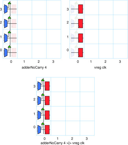
A parameterized n-bit registered adder can be defined as:
registeredAdder :: Int -> Bit -> ([Bit], [Bit]) -> [Bit]
registeredAdder n clk = adderNoCarry n >|> vreg clk
The Virtex layout produced for registeredAdder 4 is shown below.
Next section: An Adder Tree in Lava